 How to Combat Uplink Power Loss
by Tore N. Anderson and Dr. Ronald S. Posner
Antennas for Communications
Reprint from Satellite Communications, January 1995
Table of Contents
- Introduction
- Uplink Earth Station Design
- Oversized Multimode Waveguide
- Transition from Waveguide to Tallguide ®, Tallguide Bends and Twists
- Tallguide Mode Suppressor to Eliminate Trapped Modes
- Decrease in Power Loss
- Figure: Tallguide Loss Savings Compared with Standard Waveguide
for Satellite Communications Frequency Bands - Table: Example Calculations for Transmission Loss Comparison between
Tallguide and Standard Waveguide
Return to AFC ProfileReturn Tallguide Home Page
Introduction
 |
Top of Page Return to AFC Profile
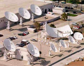
Uplink Earth Station Design
There are no unique answers to questions involving the design of two-way satellite earth stations. Different solutions are a testament to individual ingenuity. Numerous factors affect the engineering of satellite earth station uplinks. These include the receive earth station antenna size and noise temperature, the satellite transponder parameters, the information modulation scheme and bandwidth, data rate and error correction coding, frequency, path loss, adjacent satellite interference, operational reliability, and all kinds of environmental ingredients. Operational reliability and environmental contingencies go hand-in-hand. To minimize signal outages, allowances are made for rain fade and antenna pointing deflections caused by wind, installation errors, and controller pointing accuracy. As a computational aid, each contribution is added to a spread sheet. When totaled, what is left is an algebraic equation relating the uplink EIRP to a signal quality measure such as video carrier-to-noise ratio or data energy per bit. Once the required minimum information accuracy is defined, for example, in terms of picture or information quality, a numerical solution is nearly within reach. The receiver transfer function attributes information accuracy into carrier power levels or ratios. As is usual system practice, link closure is specified as the minimum uplink EIRP to achieve the crucial information accuracy. Indeed, link closure EIRP is used as a guide in all subsequent design analyses. Earth station antenna size, transmitter HPA power and waveguide run losses are each manipulated to maintain a total EIRP value.
A design engineer is faced with an infinite number of choices in any EIRP decision. Antenna size or transmitter power can be increased to offset waveguide loss. Waveguide loss can be reduced to keep antenna size, civil works and transmitter power manageable. To complicate matters even more, to achieve superior operational reliability, complex strategies can be employed, such as uplink power control, to pin EIRP demands against the local weather. It is the wealth of potential design freedoms and system needs that spearhead engineering technique.
Top of Page Return to AFC Profile
Oversized Multimode Waveguide
 Oversized multimode waveguides for ultra low loss transmission have been under investigation for many years. Historically, a few different circular waveguides have been developed for specialized applications. These include antenna feeds, straight tower runs for terrestrial microwave repeater stations and fusion energy research. As any field or design engineer knows, waveguide interfacility runs require various straight sections, bends and twists to snake waveguide from the transmitter to the antenna feed system. Nature's predicament with round waveguide, however, is circular symmetry. Over the entire run length, any imperfections or minor bends from perfect circular symmetry launch spurious waveguide modes. These modes suck away power and destroy linearity. Because of the circular waveguide electric field curvature, efficient mode suppression is difficult.
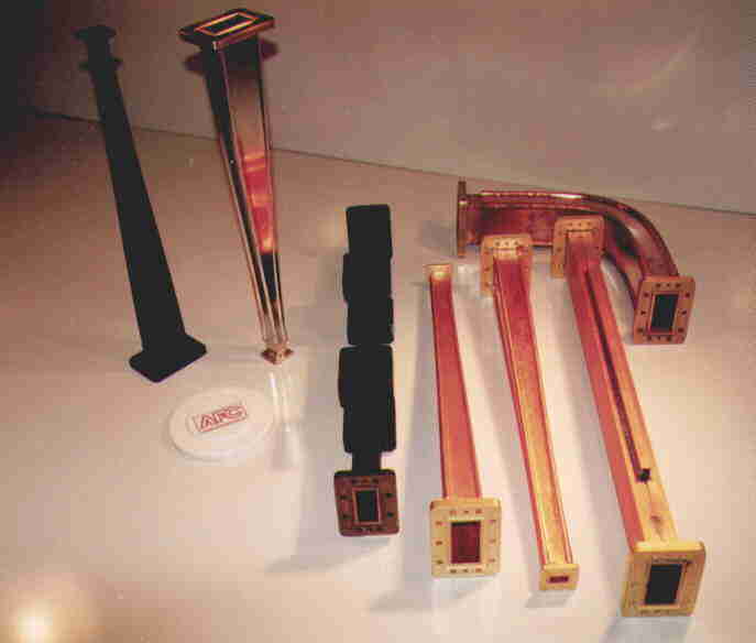
In contrast, Tallguide (TALLGUIDE ®), a tool to reduce power loss, uses precision rectangular waveguides for operation in the TE0l mode. Where ordinary waveguide electric field lines are parallel to the narrow waveguide wall, Tallguide mode electric field lines are straight and parallel to the broad waveguide wall. Each Tallguide run consists of transition units at each end (for example launching WR75 into and out of Tallguide TG115), along with various straight sections, bends, twists and mode suppressor in-between.
Top of Page Return to AFC Profile
Transition from Waveguide to Tallguide, Tallguide Bends and Twists
|
Several kinds of curvatures have been exploited to map waveguide into Tallguide and to map Tallguide into Tallguide bends and twists. Unmistakably, the most promising curvature is the hyperbolic secant curvature. Because Tallguide often operates in high power applications, several kW average power, even the smallest power conversions constitute watts of power. It is for this reason that Tallguide uses optimum curvature components. Electroforming techniques are employed to manufacture the complex internal contours and to provide high strength components.
Top of Page Return to AFC Profile
Tallguide Mode Suppressor to Eliminate Trapped Modes
Signal linearity is key in communications systems. Distortions in the communications path degrade signal quality. Subsequent signal processing, down conversions, remodulation or retransmission strategies do not improve or perfect signal clarity. In order to preserve and even enhance signal linearity, a higher order mode suppressor is inserted into the Tallguide run. No matter how insignificant the mode conversion energy is in the Tallguide interfacility run, the possibility remains that some unwanted higher order waveguide modes may be excited. Without some form of mode suppression, the unwanted higher order modes are trapped between the two Tallguide transition's ends. The trapping occurs because at some point, the Tallguide transition's cutoff narrows to single mode waveguide operation. Depending on the signal frequency and waveguide run length, the trapped energy forms a series of cavity frequencies with resonate frequency spacing.In all practical installations, the Tallguide run length is many times the wavelength. Therefore the trapped resonate frequencies form a series of very fine comb lines. Even though residual higher order Tallguide mode generation is very weak, trapped mode conversion affects linearity whenever the operating frequency coincides with one of the comb lines. It is for this purpose that the mode suppressor is introduced. With the mode suppressor, all higher order mode energy is absorbed, thereby removing the unwanted trapped energy from the Tallguide system. Further, since the Tallguide wavelength is longer than the wavelength in standard waveguide, Tallguide linearity is superior to standard waveguide. Tallguide has been tested on numerous communications and radar systems in both narrow and broad band signal modulation modes. No negative linearity effect is measured for data, video, multi-carrier video, FM, phase modulation and ultra short pulse radar signals.
The mode suppressor is a reciprocal device. Any input/output orientation is satisfactory. The mode suppressor may be placed anywhere in the Tallguide run. For high power applications, however, it is recommended that the mode suppressor be placed on the antenna side of the Tallguide system just before the Tallguide transition to standard waveguide.
Top of Page Return to AFC Profile
| DBS Band | Ku-band | C-band | ||||
| System Component | Tallguide TG87 17Ghz 90 ft. Loss | Standard Waveguide WR62 17Ghz 90 ft. Loss | Tallguide TG115 14Ghz 120 ft. Loss | Standard Waveguide WR75 14Ghz 120 ft. Loss | Tallguide TG215 5.9Ghz 400 ft. Loss | Standard Waveguide WR137 5.9Ghz 400 ft. Loss |
| Transitions | 2*0.07= 0.14dB |
2*0.07= 0.14dB |
2*0.07= 0.14dB |
|||
| H-plane Bends | 3*0.02= 0.06dB |
3*0.04= 0.12dB |
3*0.02= 0.06dB |
3*0.04= 0.12dB |
3*0.02= 0.06dB |
3*0.04= 0.12dB |
| Straight Sections | 0.87*90/100= 0.78dB |
4.98*90/100= 4.5dB |
0.635*120/100= 0.76dB |
3.73*120/100= 4.5dB |
0.281*400/100= 1.12dB |
1.88*400/100= 7.52dB |
| Mode Suppressor | 0.12 dB | 0.12 dB | 0.12dB | |||
| Flanges | 0.01*10= 0.1dB |
0.02*8= 0.16dB |
0.01*13= 0.13dB |
0.02*10= 0.2dB |
0.01*23= 0.23dB |
0.02*20= 0.4dB |
| Total Loss | 1.2 dB | 4.8 dB | 1.2 dB | 4.8 dB | 1.7 dB | 8.0 dB |
Decrease in Power Loss
Standard waveguide transmission loss over the interfacility run between the transmitter HPA in the control room and the antenna site location significantly contributes to intensified power demands. Often, waveguide power loss accounts for more than half the antenna system gain. To offset waveguide loss, engineers are compelled to beef up transmitter power, increase antenna size or move the control room next to the antenna. Such alternatives are very expensive. Frequently, existing site conditions or customer preference take away any option of moving the control room to a more favorable location.Tallguide is a means to increase uplink EIRP. Tallguide EIRP power savings are 6 times compared to standard waveguide. Moreover, interfacility waveguide loss is significantly reduced without any signal quality degradation.
Ultra low loss Tallguide removes the power loss and length restrictions of standard waveguide. At the same time, it removes the huge antenna system escalation costs needed to remedy the power loss of ordinary waveguide.
AFC manufactures, markets and sells worldwide satellite dish antennas, radomes, antenna feeds, microwave and waveguide components and ultra low loss waveguide transmission line Tallguide. Our customers serve the broadcast, communications, radar, weather and cable industry, defense, government, and government agencies worldwide. AFC's quality control manufacturing standards are certified under ISO 9001 : 2015.
More information about Tallguide, including part selection, model numbers and other frequency bands, may be found in Tallguide Ultra Low Loss Waveguide. Detailed Tallguide component information, for the satellite Ku and DBS uplink frequency bands, may found in the TG115 and TG87 data sheets. A complete Internet WWW AFC site index may be found in Antennas for Communications (AFC) Home Page Document Summary List.
Top of Page Return to AFC Profile
2499 SW 60th Ave, Ocala, FL 34474
Tel (352) 687-4121 Fax (352) 687-1203 E-mail sales@afcsat.com
Tallguide is a Registered Trademark of Antennas for Communications
Copyright © 1995 Satellite Communications
Reprint Copyright © 2017 Antennas for Communications